The Shift into DOCSIS 3.1: A Big Upgrade
 Five years following the release of the 3.0 specification, DOCSIS 3.1 became available. This technology showed a massive change from the previous iteration of DOCSIS. Up until 3.0 the modulation technique used for downstream DOCSIS was (and is) SC-QAM which stands for Single Carrier Quadrature Amplitude Modulation. In this modulation technique, a single carrier signal is modulated using amplitude and phase modulation at a specific bandwidth. The DOCSIS 3.0 specification modulates the carrier signal with up to 256 QAM (quadrature amplitude modulation) per channel.
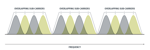 DOCSIS 3.1 leverages newer and more advanced modulation techniques called Orthogonal Frequency Division Multiplexing (OFDM) and orthogonal frequency-division multiple access (OFDMA). OFDM divides the occupied bandwidth into multiple narrowband subchannel frequencies as opposed to only one wideband channel. OFDM consists of multiple orthogonal subcarriers that can each be modulated with a different modulation order, therefore you can efficiently use the bandwidth instead of using specific bandwidth transmit only. Since subcarriers are orthogonal, they can be spaced closely without any guard bands. This results in more efficient usage of the bandwidth and leads to higher data rates and better performance in challenging network conditions. OFDMA, as multiple access implies, is similar to OFDM which takes a channel and subdivides it, but it can assign these subchannels to many devices and frequencies more efficiently over time. By employing higher and more efficient modulation orders as 1k-QAM to 4k-QAM instead of the 256 QAM, cable providers can pack in more bits per hertz.
These changes brought massive benefits to the protocol including:
- Easy adaptation to severe channel conditions.
- Efficient use of the spectrum by sharing the spectrum between several users with multiple access technology.
- Reduction of interferences.
- Flexible modulation schemes.
Concurrently, a change of this magnitude made the rollout much more complicated than previous specifications. Rolling it out was (and is) a major undertaking and didn’t happen overnight. Multiple system operators (MSOs) required complete hardware redesigns and this became a major cost for the deployment for new cable modem termination system (CMTS) passive and active devices. In some cases, the infrastructure itself needed to be redesigned. For instance, the 85MHz upstream band which is referred to as 'mid-split' was significantly less problematic as existing DOCSIS 3.0 equipment uses the same bandwidth; however, the 204MHz band which is called 'high-split' required equipment changes, including the customer premises equipment. Additionally, the network required an upgrade to raise the upper limit of the downstream spectrum. This was quite challenging as it required replacing both passive and active devices.
Network Bandwidth and Channel Expansion
Since DOCSIS 3.1 allowed for network expansion in both upstream and downstream as needed by the operators, an important aspect of DOCSIS 3.1 is that it operates on existing HFC networks. Those networks can be updated to accommodate more bandwidth, as outlined in the DOCSIS 3.1 specification:
In the downstream direction, the cable system is assumed to have a pass band with a lower edge of either 54 MHz, 87.5 MHz, 108 MHz or 258 MHz, and an upper edge that is implementation-dependent but is typically in the range of 550 to 1002 MHz. Upper frequency edges extending to 1218 MHz, 1794 MHz and others are expected in migrations of the plants to increase network capacity.
In the upstream direction, the cable system may have a 5-42 MHz, 5-65 MHz, 5-85 MHz, 5-117, 5-204 MHz or pass bands with an upper band edge beyond 204 MHz.
What is the latest DOCSIS version?
After the implementation of DOCSIS 3.1, customers continued to demand higher speeds and more bandwidth. In DOCSIS, the demand always drives the technology. So, while some will continue to pursue the introduction of multi-gigabit services, there are other benefits to broadband connectivity. It is the reliable network and low latency that drives the DOCSIS industry to extend HFC investments and continue on the path to 10G. DOCSIS 3.1 has a set limit for upstream and the market is showing that it is not high enough. The usage is growing by 50% every year, and at this rate the maximum capacity for upstream will quickly be surpassed. Additionally, the demand isn't limited to symmetric multi-gigabit speed over HFC networks, but it is for low latency, constant jitter and reliability. These were the drivers to move into DOCSIS 4.0 and 10G, which is the next step. 10G offers higher speed, more reliability, better security and lower latency.
Today, MSOs must boost the upstream speed and capacity by increasing both the bandwidth of downstream and upstream. DOCSIS 4.0 has a broader frequency range for upstream and downstream at 684 MHz which has the potential to deliver speeds of 10 Gbps for downstream and up to 7 Gbps upstream.
DOCSIS 4.0
To achieve these results, DOCSIS 4.0 comes in 2 different flavors. These are Frequency Division Duplex (FDD) and Full Duplex DOCSIS (FDX).
Frequency Division Duplex and Full Duplex DOCSIS (FDX)
FDD mode is essentially an extension of DOCSIS 3.1, leveraging the same technology. It is also known as Extended Spectrum DOCSIS (ESD) which implies that it extends the upstream-only spectrum and the downstream-only spectrum independent of one another. With FDD, 5-85 MHz is used for legacy (like the previous revision) while the upstream spectrum can be extended as high as 684MHz. This leaves 108-684MHz for upstream-only and it introduces four new split options: 300 MHz, 396 MHz, 492 MHz and 684 MHz. FDD also introduces an expansion to the downstream spectrum to 1.8GHz. MSOs can offer more bandwidth and higher data rates for both upstream and downstream, and it is symmetrical. 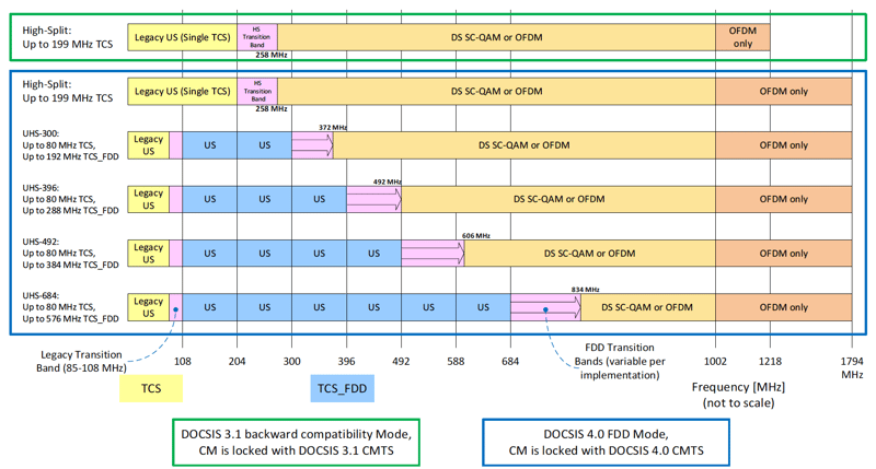
Source: Data-Over-Cable Service Interface Specifications DOCSIS® 4.0 -CableLabs
On the other hand, FDX is a new technology that hasn’t been used before.FDX technology improves capacity by enabling network devices to simultaneously transmit both downstream and upstream channels in the same 108-684MHz spectrum. Additionally, the downstream-only spectrum further extends up to 1.2GHz. The increasedupstream capacity with FDX is within the shared spectrum and it is more flexible and efficient. Different users can use the 108-684 band for different purposes and there are no issues. Since downstream and upstream transmissions share the same spectrum a new echo cancellation technology is required to make FDX a reality. It is the cable modem (CM) that must to stop any interference caused by the shared spectrum which it could increase the complexity of the equipment such as node, cable modems and amplifiers. Since the 3.1 architecture and FDD do not have this shared spectrum it is not a concern there.
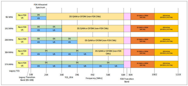
Source: Data-Over-Cable Service Interface Specifications DOCSIS® 4.0 -CableLabs
MSOs have the flexibility to pick the technology they will be moving forward with, whether that is FDD or FDX, but cannot choose to do both; the difference between the deployment approaches and required equipment makes it is too expensive. It is undecided which is preferred but CableLabs has developed 4.0 specifications for both technologies.
The initial release of the 4.0 specification was in August of 2019. It has been revised several times and will continue to be. This specification includes what is in the PHY layer, what is in the MAC layer and how systems must communicate in terms of DOCSIS 4.0. The PHY layer refers to the physical layer of the open system interconnection model (OSI). It manages bit-level transmissions between devices and helps synchronize communication. The MAC layer has the necessary functions to operate the network.
As for silicon availability, there are many options as very few chip makers focused on DOCSIS 4.0. Based on MSOs news and trials, there is silicon for FDX and FDD devices, including remote PHY and cable modems. Both Broadcom and Maxlinear are reported to be involved in developing silicon for DOCSIS 4.0.
As FDD and FDX are so different in nature that the deployment of these technologies are very different from one another.
FDD is essentially an extension of D3.1 it should be easier to deploy, but due to the wider band, the plant must be prepared. FDD utilizes the spectrum from 1.2GHz and 1.8GHz which requires the plant to replace active and passive devices, like taps and amplifiers. This is very complex and expensive. Up until now amplifiers were only reaching up to 1 GHz, which is not enough to support this extension. As of 2023, newer amplifiers were beginning to hit the market, so a solution is underway.
FDX has been envisioned as applicable to the N+0 topology, which is nothing but fiber networks that run close to the home, also known as fiber-deep. The N signifies the node and the number represents the number of amplifiers it will require. As it is zero, no amplifiers are required. However, once FDX amplifiers start to hit the market, the N+0 topology ends up being a costly solution and unsuitable option for the majority of the cable footprint. Rural areas without the proper infrastructure in place must be considered.
Tools and Strategies for Network Bandwidth and Channel Expansion
Planning and implementing these extended bandwidths will, of course, require new tools and strategies. Some elements that will need to be deployed to accommodate the changing frequency spectrum include:
- A protocol analyzer capable of covering the entire frequency band. This will minimize capital expenditures as the operators start to use the upper frequency bands.
- Downstream and upstream channel configurations that allow operation in the different bands.
- Modular instruments that enable system capabilities to be upgraded and extended as network needs evolve with additional features and functions using the same hardware and components.
- Multiple systems that can be synchronized in order to offer extended coverage and analysis of the DOCSIS band.
Testing DOCSIS 4.0
 Before a CM can hit the market, it must be certified against CableLab’s acceptance test procedures or ATP for the PHY layer. All devices must complete a series of tests for compliance with the applicable specification to demonstrate interoperability with other certified devices. Interoperable devices based on common specifications facilitate consumer choice, successful deployment of new technologies, and lower costs to MSOs and consumers. MSOs must send their modems to Kyrio for certification. They run all of the ATPs for all of the different PHYs and compare them to the specification.
That is why automating the ATP is crucial. To perform these tests manually would take months to do and cannot guarantee consistency or repeatability. An automated test system cuts the test time down exponentially and delivers reliable and reproducible results each time. There will always be the same data, and the same accuracy regardless of how many times the tests are run.
Averna is an expert in DOCSIS Testing
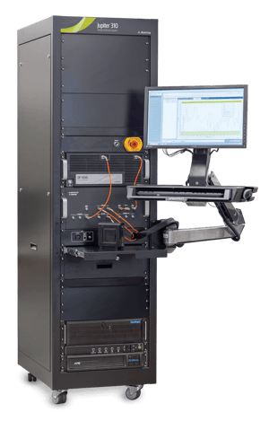
The Jupiter 310 CPE design verification system has been developed by Averna to automatically run the PHY ATPs for DOCSIS 3.0, 3.1 and 4.0. Chipset manufacturers all over the world leverage this instrument to assure certification with Kyrio. It is hugely important for all the tests to pass, because it can become a very expensive and time-consuming endeavor the more often a CM is sent in to be certified. To avoid any test failures, companies keep their own J310 onsite to pre-qualify and resolve any discrepancy against the ATP before sending their product to Kyrio. It also quickly generates the required documentation companies require for traceability.
DOCSIS Protocol Analysis
At a basic level, network operators can perform protocol analysis, often called "packet sniffing," to capture packets and decode them into their component parts, especially for troubleshooting communication issues. While this is the traditional application of protocol analyzers, they can actually do much more than packet sniffing; for example, they can be surprisingly useful in many aspects of network management for analyzing, debugging, maintaining and monitoring local networks and Internet connections.
By providing statistics on network traffic, protocol analyzers can play a valuable role helping MSOs identify trends that may lead to further network problems. Since these tools are versatile, they can be used by a variety of individuals who have network responsibility or by anyone who needs to better understand traffic issues. A protocol analyzer may be used for various scenarios such as:
- Troubleshooting real-time outage and service interruptions
- Analysis of strange network behavior
- Producing real-time and historical statistics to help observe link health and behavior over time
- Lab testing and validation
For the past few decades, protocol analysis tools have proven to be effective solutions for debugging and resolving network issues. Due to the changing nature of networks, a protocol analyzer needs to be flexible, upgradable and extendible to handle evolving protocol standards such as DOCSIS 4.0. It must also remain backwards compatible. A protocol analyzer’s non-intrusive network probing, combined with its ability to take RF measurements and perform MAC-level communication analysis, can provide that additional level of monitoring. Important functions of a protocol analyzer include: 
- Validation of MAC-level communication including:
- Validating that a message from a CMTS or CM is properly formatted.
- Verifying that some transactions between the CMTS and the CM (e.g., REQ/RSP/ACK mechanisms) properly take place under normal conditions.
- Verifying how the CMTS or CM reacts to some events by analyzing the content of the resulting MAC messages.
- Real-time demodulation. Applications can include:
- The real-time demodulation and display of the OFDM channel descriptor (OCD) to provide useful information for debugging a CMTS and understanding why the CM is not locking.
- Providing additional monitoring capabilities by allowing the operator to enable alarms and threshold alerts.
- Triggering capabilities:
- A capture trigger, which can be configured for specific types of messages or a destination source (MAC) address.
- A hardware trigger, which can be configured for specific types of messages. This option allows other devices and equipment – such as a spectrum analyzer or even integration into a custom solution – to extend DOCSIS testing scenarios and possibilities.
- Recording capabilities for communication packets
- Support for multiple protocol standards.
This new DOCSIS standard brings its share of complexities, thus next-generation protocol analysis tools should be flexible enough to handle the existing DOCSIS standard, the new DOCSIS standard’s strict requirements, and its evolution. Such tools will enable operators – both in real-time and offline – to efficiently monitor, analyze and troubleshoot their networks in many practical and beneficial ways.
Follow Our Test Guru!
Get up to speed with the latest tech trends, best practices and tips shared in our eBooks, white papers and more.